This product is no longer available.
 The DSP56002EVM is a low-cost Evaluation Module (EVM) designed by
Motorola to familiarize engineers and experimenters with the Motorola DSP56002
Digital Signal Processor (DSP) chip. The DSP56002EVM is very popular with
Amateur Radio enthusiasts interested in DSP techniques. The EVM has been programmed
to perform as a 1200 AFSK modem, 9600 bps FSK G3RUH modem, and
various filters, just to name a few.
The DSP56002EVM is a low-cost Evaluation Module (EVM) designed by
Motorola to familiarize engineers and experimenters with the Motorola DSP56002
Digital Signal Processor (DSP) chip. The DSP56002EVM is very popular with
Amateur Radio enthusiasts interested in DSP techniques. The EVM has been programmed
to perform as a 1200 AFSK modem, 9600 bps FSK G3RUH modem, and
various filters, just to name a few.
The DSP56002EVM was made popular by Johan Forrer, KC7WW, in the August 1995 QEX article entitled "Using the Motorola DSP56002EVM for Amateur Radio DSP." Johan created a software package for the DSP56002EVM.
Greg Jones, WD5IVD, President of TAPR, arranged for TAPR to have access to a large number of evaluation units from the Motorola DSP group. The purpose was to distribute these units to the amateur radio community for the support of DSP related research and development. Over a three year period, TAPR provided over 500 evaluation units into the amateur radio community.
The DSP56002EVM was discontinued by Motorola, but EVMs do appear on eBay or amateur radio for sale web pages.
Resources
- Using the Motorola DSP56002EVM for Amateur Radio DSP Projects
- The DSP Experimenters Homepage
- DSP Special Interest Group - Discusses the DSP56002EVM and other general DSP topics
- TAPR DSP Software Archives
- KC7WW's Collection of Utilities and Application Package for the DSP56002EVM
- Danie Brynard, ZS6AWK Interface
- Jabi Aguirre, EA2ARU Interface
Documentation
For technical documentation on the DSP56002 and other DSP chips manufactured by Motorola. Visit the Motorola Digital Signal Processing web page. The DSP56002 Technical Documentation page has a link to DSP56002EVM Documentation and an overview of the DSP56002 chip.
Prentice Hall has published a text book entitled "Digital Signal Processing Applications With Motorola's DSP56002 Processor, 1/e" by Mohammed El-Sharkawy, Copyright 1997, ISBN 0-13-569476-0.
Using the Motorola DSP56002EVM for Amateur Radio DSP Projects
Motorola's low-cost DSP evaluation module covers all the bases for amateur use and development.
By Johan Forrer, KC7WW
Originally published in QEX August 1995
This article is about the Motorola DSP56002EVM, a low-cost,
powerful DSP evaluation module (EVM) intended for those experimenting with
digital signal processing (DSP). It is ideally suited for filtering CW
and EME signals, audio processing applications such as denoising and autonotching
and DSP modem work for HF digital and VHF/UHF modems for use in terrestrial
and satellite applications. I'll cover hardware and resources for application
development and present a collection of advanced DSP applications ready
for amateur experimentation. (See the Collection of Utilities and Application Package for the DSP56002EVM that appeared with this article.)
Background
One way to learn about new computer hardware, especially
processor chips, is to actually try your hand at programming them. Unfortunately,
for an amateur experimenter with limited resources, mastering a complex
processor like the Motorola 56002 DSP is a formidable task. This is not
something for the faint of heart.
The recent introduction of low-cost EVMs by DSP chip manufacturers,
however, has helped make DSP technology available to experimenters. These
EVMs include sufficient educational materials to get you started: a small
printed circuit card that contains the DSP chip, software to develop and
evaluate educational programs and essential technical reference material.
In an amateur-radio environment where cost and availability are major factors,
these EVMs have been received with great enthusiasm. The DSP56002EVM is
Motorola's entry into this market. The DSP56002EVM may be used either as
a DSP development platform or for a free-standing application when using
its onboard E(E)PROM memory. The DSP chip used on the EVM has an impressive
track record in communication engineering. Its DSP chip is from the same
Motorola DSP family as the chips used in the HAL PCI-4000 [1],
AEA DSP 1-232, DSP 2-232 [2] and the DSP-12 [3]--and
even in commercial and military products. If judged by these success stories,
the 56002 presents splendid opportunities as it offers high clock speed
and the advantages of its on-chip hardware emulator.
A Peek at the 56002 DSP
The computing engine of the DSP56002EVM is a 40-MHz 56002
DSP. This is a 24-bit processor, meaning that each instruction is 24 bits
wide. Data and instruction words are kept in separate memory spaces. Instructions
are stored in the "P"-space, short for program space. Two separate,
independent data spaces, "X" and "Y" are available.
This separation of data and instructions is called a Harvard architecture.
This is quite different from the Von Neumann architecture used,
for example, in the 80x86 processors. The Harvard architecture is typically
used in DSPs and allows for extensive instruction parallelism.
The value of this parallelism becomes evident when one considers
that the strength of DSP processors lies in their ability to multiply and
accumulate (MAC) very efficiently. The 56002 scores high in this regard.
It can multiply two operands, accumulate (sum) the result, fetch two new
operands from its two independent data spaces, do address adjustment and
fetch the next instruction--all in one clock tick. For a 40-MHz 56002,
this happens 20 million times per second. Other DSP chips may have similar
features, but having two data spaces and a 24-bit code/data architecture
is a distinguishing feature of the 56000 family.
The 24-bit architecture of the 56002 allows a richer instruction
set than that of comparable 16-bit DSPs. It also allows an impressive selection
of extended addressing modes. These addressing modes are available in one-word
instructions and also in a two-word instruction format. Which instruction
format to use becomes a trade-off between ease of programming and programming
for efficiency. Obviously, the additional dynamic range of 24-bit data
(144.5 dB) over 16-bit data (96.3 dB) may prove valuable in certain applications.
Higher computational accuracy, or perhaps the ability to detect weaker
signals buried in noise, is possible.
The 56002 allows for a considerable degree of flexibility
in interfacing configurations. Access by the outside world to the DSP is
through several I/O pins, arranged as general-purpose I/O ports named,
"PA," "PB," and "PC." Depending on the application,
several of these I/O pins double up for use as signals for onboard peripherals
such as a synchronous serial interface (SSI) or serial communications interface
(SCI). When using these on-chip peripherals in applications, some of these
I/0-port pins become dedicated and are no longer available for general-purpose
I/O. Port PB in the DSP56002EVM is available at header J7 and is available
for the user's interface. Initialization and use of these peripheral devices
are documented in the 56002 user's guide. [4] Other
DSPs have similar peripherals, particularly with respect to their capability
to directly interface high-speed CODECS. But the 56002 SCI and OnCE peripherals
are unique for the class of fixed-point DSPs.
The 56002 user-programmable phase-locked loop (PLL) determines
the DSP clock rate. A 4-MHz crystal clock is available on the EVM to drive
the PLL. This clock, incidentally, also serves as the clock for the on-board
6805 OnCE-interface microcontroller. Such a programmable system clock may
serve several purposes. It may allow the designer to meet a variety of
internal timing constraints. Or for portable equipment, a variable clock
rate may be used for power management. The DSP consumes more power at higher
clock rates than lower rates. Power consumption may thus be regulated by
selecting the lowest internal clock rate that meets the requirements of
the application.
One extremely useful feature of the 56002 is the inclusion
of an on-chip sine-lookup ROM that comes in handy for use in communication
applications, especially numerically controlled oscillators (NCO) for demodulators.
An Overview of the DSP56002EVM
Figure 1 shows a much simplified overview of the basic hardware
components of the DSP56002EVM.
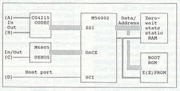 |
CODEC Interface (SSI)
A Crystal Semiconductor CS4215 coder-decoder (CODEC) handles
analog signal conversion. This chip is designed for high-quality multimedia
audio purposes and is capable of converting two analog signals to 16-bit
digital values (A/D). It also contains two 16-bit digital-to-analog (D/A)
converters. These A/D and D/A converters form the analog input and output
capabilities of the EVM. The CS4215 is a flexible device, capable of a
variety of user-programmable data conversion rates, programmable input
gain and programmable signal output attenuation. The CODEC interfaces with
the DSP via the DSP's SSI using a minimum of interface signals. DSP software
must initialize the serial clock rate and framing method of the SSI for
the particular CODEC. Additional control lines for reset, and data/control
select, are required to fully command and control the CODEC. In the EVM's
case, these control signals are assigned from peripheral port "C,"
as shown in Table 1.
|
M56002 port C |
Function |
|
0 |
SCI Receive (host port) |
|
1 |
SCI Transmit (host port) |
|
2 |
CODEC Data/Control (D/C) |
|
3 |
Not used (used for DCD in Leonid code) |
|
4 |
CODEC reset |
|
5 |
CODEC Frame synchronization |
|
6 |
CODEC Serial clock |
|
7 |
CODEC Receive (SSI Rx) |
|
8 |
CODEC Transmit (SSI Tx) |
Note that the DSP56002EVM only implements a subset of the
CS4215's capabilities. Of particular importance is the following: There
is only provision for "mike" input, as the line input is disabled.
Only one crystal is used, 24.576 MHz, which is connected to the "XTAL2"
position of the CS4215--this normally is reserved for a 16.9344MHz crystal.
XTAL2 must be selected when initializing data sampling rates. Typically,
8, 9.6, 16, 27.42857, 32 and 48-kSPS rates are available. These are commonly
used rates for communications applications.
On-Chip Emulation (OnCE) Interface
A 6805-family microcontroller greatly simplifies the OnCE
debugging interface. This single-chip solution not only saves board space,
but also helps to keep costs down. Its purpose is to translate commands
received via the serial interface from the PC-hosted debugging software
into parallel control commands for controlling OnCE operation. The low-level
OnCE interface logic is very intricate, consisting of several handshaking
strobes and intricately-timed pulse sequences--not an easy task to program.
The 6805 microcontroller takes care of all this low-level complexity and
hides a great number of details from the user without restricting the capabilities
of the OnCE, or perhaps only to a small extent: speed. The microcontroller,
in its present form, is only capable of operating at a maximum speed of
19200 baud. At this speed, large DSP programs may take a while to download.
Although it is not crucial for a developer to know about
the low-level debugger interface protocol to use the DSP5600EVM, it may
be valuable when embedding OnCE capability into your own programs, or even
to make it possible to use the EVM on other, non-DOS platforms. A summary
of the OnCE interface protocol follows. [5]
Communication with the 6805-family microcontroller is eight-bit
serial at 19200 baud. The host issues a command code that may consist of
a single byte or may be multiple bytes, depending on the command. The response
from the microcontroller is also coded, consisting of a single byte or
multiple bytes. In certain situations, such as reset, there is no response,
in which case the host should confirm that the EVM is in a usable state
by a status query. Table 2 summarizes the command structure.
|
Host (Hex) |
Purpose |
EVM Response (Hex) |
| A0 Rx | Read OnCE register Rx | D7 RaRbRc (4 bytes) |
| A1 Wa | 1-byte write | D1 - success, D2 - failed |
| A2 WaWbWcWd | 4-byte write | D1 - success, D2 - failed |
| A3 | Reset DSP | no response |
| A4 | Reset DSP | no response |
| A5 | Force OnCE into debug | D3 - DSP dead D5 - success |
| A6 | Release OnCE | D4 - success |
| A7 | Read DSP status | D7 Sa (2 bytes) |
| A8 | ..not used | |
| A9 | Reset the 6805 | no response |
| AA-AB | ..not used | |
| AC | Check if 6805 is alive | D6 - 6805 responding |
| AD | Obtain what code level | La - code level |
Host Port Interface (SCI)
The ONCE port is mainly used for debugging purposes. A more
traditional serial interface is provided by the SCI. The DSP56002EVM provides
a host connector (an optional feature) for this purpose. When the SCI interface
is used, PC0 is programmed for SCI data receive and PC1 for SCI data transmit.
(These assignments are also shown in Table 1.) Applications that use this
interface for communicating with a host may use either ASCII or KISS format.
[6] In stand-alone mode, the SCI port is the only
means of communication with the EVM. Note that there is no provision for
hardware flow control on the DSP560902EVM in its present form--applications
must provide software flow control when needed.
Static RAM Memory
The 56002 DSP has 1024 24-bit words of on-chip static RAM
(SRAM) that is divided as 512 words of P-memory, 256 words of X-memory,
and 256 words of Y-memory. This on-chip memory runs at processor speed
and usually is reserved for code that needs to run at the fastest possible
speed, such as critical interrupt handlers or variables that need to be
accessed very often.
An additional 32K words of SRAM is provided by three (32K
x 8) 6206A SRAM chips. Dealing with address decoding logic for these fast
DSP chips is very tricky due to the short access times and propagation
delays in decoding logic. The EVM designers opted to use a simple, effective
method of partitioning the address space. Address lines 14 and 15 and enables
X/Y effectively allow for two addressing schemes. These are selected by
jumper J12 (16K/32K). The resulting memory layouts are shown in Figure
2.
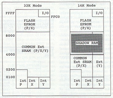 |
Both schemes lead to compromises--for example the 32K scheme
has P, X and Y all residing in the same physical space. The programmer
then has to guard against aliasing side-effects. For example, address P(220)
is the same physical RAM location as X(220) or Y(220). In the 16K scheme,
on the other hand, P and X share the same space with Y being independent.
In this case, the programmer should watch out for aliasing P and X RAM
locations. In addition, memory locations above 4000 are "shadow"
RAM, that is, address decoding does not distinguish between locations in
the range (0000 to 3FFF) and corresponding locations in the range (4000
to 7FFF).
These peculiarities have led programmers to take advantage
of the hardware in clever ways. One programming trick that is often used
to speed up DSP algorithms on the 56002 is to use a single location pointer
for addressing two equal-sized I/O buffers. For example, let one buffer
be used as a data source and another for a data destination. If X and Y
are then set such that the corresponding elements of the input and output
buffers reside at the same numeric address, for example: Input(10)is at
address X(080), Output(10) is at address Y(080), then a common single pointer
register (R2 in this case) does both fetching and storing of data at the
appropriate locations.
    move   X:(R2),x0    ;Input comes from X
   move   y0,Y:(R2)    ;Output goes to Y
An example of how this is used can be found in the Leonid
kernel's CODEC interrupt handler, where code efficiency is crucial. Some
of these peculiarities become important considerations when porting 56002
code across different platforms. The amateur-radio application programs
in this article all use the 16K memory mapping.
One fact that is often overlooked pertains to external RAM:
No matter which scheme is used, any data accessed in off-chip RAM involves
multiplexing/demultiplexing of the address and data busses--the ultimate
penalty is speed of execution. It is thus imperative that time-critical
code reside in the on-chip RAM if at all possible.
Memory E(E)PROM
The DSP56002EVM includes an option to use an E(E)PROM for
booting. This is essential for stand-alone applications. An EPROM such
as a 27C256 would be suitable, but this assumes that the user has access
to all the necessary tools to convert 56002 object code to a form suitable
for booting the DSP. A much more elegant and useful alternative is to use
an EEPROM, such as the Atmel At29C256PC FLASH PROM. It is relatively easy
to program this device in-place using the software tools supplied with
the DSP56002EVM.
Other Miscellaneous Glue Logic
Besides the DSP, CODEC and 6805 OnCE interface, very little
additional logic is required to make a functional system. Shifting RS-232
levels to logic levels is handled by a MAX232--both transmit and receive
pairs for the OnCE and host interface port are provided for. The 56002
reset logic also requires attention, as the DSP can be forced into one
of several operating modes at reset time by presenting the hardware with
a special reset signature. For the DSP56002EVM, a 74LS157 chip is used
to present a binary "100" pattern to IRQA~, IRQB~, and NMI~ that
places the DSP in "EPROM BOOT" mode. [4]
Upon recognizing this state, and if a valid E(E)PROM device exists, the
DSP's internal boot ROM then performs a bootstrap from this ROM, regardless
of whether the ONCE port debugger is used or not.
Development Software and Tools for the DSP56002EVM
The DSP56002EVM ships with the Motorola 56002 version 5.3.2
assembler, Domain Technologies version 1.02 debugger and some (minimal)
coding examples. [7] The assembler, as far as I can
tell, is very similar to Motorola's professional edition. It generates
COFF-format object code. No loader (a program that combines several preassembled
objects) is used. This implies that all assembly code is assembled in one
step--something that may become awkward when dealing with large projects.
The generous use of include statements to read in different source
code modules is one solution that helps. However, some public-domain software
that includes a C language compiler, assembler, linker and 56000 simulator
is available that may be of interest. [8]
Domain Technologies, Inc, developed Debug-EVM for the DSP56002EVM.
This debugger bears similarities to professional in-circuit emulators in
both appearance and capabilities. Such sophistication is made possible
by the 56000 OnCE interface that effectively provides in-circuit emulation
capability on silicon. Debug-EVM provides access and control over the internal
workings of the DSP, memory and peripherals during the debugging process.
Debug-EVM is a DOS-based program that interfaces to the DSP56002EVM
through a serial port at 19200 baud. Well-organized multiple-window displays
allow for viewing data, program code, DSP registers and processor status
in various formats. During the debugging stage of code development, DSP
code and data is downloaded from the host PC to the DSP's memory. The developer
can then manipulate registers and data, and place breakpoints as required.
It also is possible to interact with a running DSP in a non-intrusive manner.
This means that the DSP may be debugged at full speed. The debugger offers
the following features:
- fully symbolic (data and code labels)
- source level debugging
- on-screen editing
- mouse support
- built-in assembler/disassembler
- character graphics (for plotting memory arrays)
- multiple memory display modes
- trace with count
- single step with count
- subroutine jump
- true real-time hardware breakpoint
- up to 128 software breakpoints
- up to four memory windows
- requires no on-chip monitor code
Amateur-Radio Applications for the DSP56002EVM
The software examples that come with the DSP56002EVM contain
only the bare minimum to get you started. One of the included routines
is a CODEC support routine, CODEC.ASM. This routine contains a collection
of functions that initialize the CODEC and get it up and running. It is
a complicated piece of code that requires that the programmer be knowledgeable
of both how the CODEC chip works and also all the intricacies of the 56002
SSI interface. Fortunately, the use of define statements makes setting
up the CODEC a fairly routine procedure. Transferring data to and from
the CODEC is fully interrupt driven using agreed-upon buffer locations.
To make the DSP56002EVM more useful to other experimenters,
I've put together a program package of useful additional programs. A listing
of the programs included in the package is shown in Table 3.
|
Native DSP56002EVM applications (KC7WW) |
| INOUT.ASM -- CODEC talk-through test
RTTY.ASM -- KC7WW's HF RTTY/AMTOR/Pactor (use with PCTOR) RCOEFFS.ASM -- filter coefficients for above TTYCD.ASM -- CODEC support for RTTY modem EVM56K.PLT -- KC7WW's EVM radio interface schematic (HPGL) EVM.PS -- KC7WW's EVM radio interface schematic (Postscript) |
|
Ported applications based on the Leonid kernel |
| TALK.ASM -- INOUT equivalent for Leonid
BIOS BIOS.ASM -- The source for the ported Leonid kernel BIOS.CLD -- loadable module INTEQULC.ASM -- essential include files IOEQULC.ASM LEONID.ASM -- KC7WW's ported Leonid include file FSK.ASM -- Jarkko's 1200 baud Bell 202 modem for the EVM BANDPASS.ASM -- Jarkko's narrow CW filter COEFF.ASM -- filter coefficients for above QRMQRN.ASM -- a slightly modified version of Jarkko's LMS denoiser |
|
Contributed programs by Jalocha, SP9VRC |
| CORELNW.ASM -- Correlation-based filter
FFT-CUT.ASM -- Denoiser based on the spectral subtraction PARLL1.ASM -- Early experimental 12-tone OFDM HF modem |
The native DSP56002EVM programs work with the code that came
with the EVM--the Leonid kernel is not used. As the simplest code example,
the INOUT.ASM program is particularly useful to a beginner to verify the
operation of the EVM and carry out some experiments with the CODEC. RTTY.ASM
is a bit more advanced and requires further background in FIR filter design.
Note that it uses a modified version of the CODEC support routines. The
program contains a thorough description of how the DSP modem works. A schematic
for a radio interface is included for use with this program.
One code module that may be of general interest is the author's
port of the Leonid kernel. This module runs some exciting amateur-radio
programs developed by the Finnish Alef Null group. [9]
The Alef Null group has been active in the development of DSP projects
since 1992--the DSP CARD 4 is their fourth generation DSP card. The DSP
CARD 4 is very similar to the DSP56002EVM in many respects, except that
it uses a 56001. However, the DSP CARD 4 is a forerunner of the DSP56002EVM.
The striking similarity in hardware and software allowed the author to
port the Alef Null software to the DSP56002EVM.
Porting Alef Null programs requires only minor changes: pay
careful attention to the CODEC input source, P, X, Y and L memory allocation.
Then, preload BIOS.CLD before loading the Alef Null application. Finally,
start the application using "GO 0." This allows the last-loaded
application to gain access to the low-level kernel services. Review the
included code examples in the experimenter's package for further details.
The experimenter's package would not have been complete without
the contributions of Pawel Jalocha, SP9VRC. These include several excellent
examples for advanced DSP experimenters. Pawel has been particularly helpful
in including assembly directives that makes his programs run on both platforms.
A Brief Overview of the Leonid Kernel
A DSP kernel is loosely defined as a sort of "command
module": a collection of DSP-resident code functions that control,
manage and interact with a user's DSP application. An in-depth overview
of a complex piece of DSP code the size of the Leonid kernel is beyond
the scope of this article. I encourage you to obtain the Alef Null documentation
and read it together with BIOS.ASM. The code is reasonably well commented.
The Leonid kernel consists of two parts: the low-level BIOS
and a higher-level abstraction that contains several macro calls. The low-level
BIOS is contained in BIOS.ASM while the higher-level macro calls are contained
in LEONID.ASM. Be sure not to mix the ported versions with the original
Alef Null code--these are not quite compatible.
The Leonid kernel contains several critical components necessary
for amateur-radio networking applications. A low-level routine handles
the HDLC protocol for assembly and disassembly of AX.25 data packets. In
addition, the KISS protocol is used together with the HDLC routines. It
is thus possible to use the DSP56002EVM with a TCP/IP (NOS) program without
any additional hardware. All that is required is the radio, EVM and a PC
running NOS. Besides these support routines, additional low-level support
is also included for time-out detection and carrier detect--necessary requirements
to successfully operate in a network environment. Jarkko's Bell 202-compatible
1200-baud FSK modem (FSK.ASM) is a good example that gives further insight
into how this all is put together.
| (1) Initialize CODEC: ctrlcd 1,r2,buflen,MIC,0.0,0.0,LINE|HEADP,0.0,0.0 |
| (2) Start CODEC: opencd 16, NOHPF Jump via P(0028) |
| (3) Collect data from the CODEC: waitblk r2, buflen, batch |
A few hints may help you follow the interrelation of the
different program modules. Figure 3 illustrates how a user program interacts
with the kernel. Examine this in conjunction with TALK.ASM, a simple example
that illustrates how to use the Leonid code and BIOS. The TALK program
starts by initializing the CODEC using the "ctrlcd" call (step
1 in Figure 3). This is a macro call (defined in LEONID.ASM) that primes
the CODEC's buffers and prepares various pointers and registers that work
with the CODEC. The parameters used in the example shown are as follows:
1--initialize data buffers.
r2--use R2 as a data pointer for reading/writing to the CODEC's
buffers.
buflen-defines the internal size of the CODEC's circular
buffers.
MIC--A define that activates the microphone as input source.
0.0, 0.0--sets the left/right input gain (see CS4215 data
sheet). [10]
LINE|HEADP--defines that activate line/headphone output.
0.0, 0.0--sets the left/right output gains (see CS4215 data
sheet).
The CODEC is started in step 2 using the "opened"
call. This macro requires two parameters: the first is the sampling rate
(ie, 16 means 16 kSPS), the second is whether the on-chip high-pass filter
is required or not (see the CS4215 data sheet for its implications). Note
that this macro includes a jump instruction to P-address 0028. This location
is part of a jump table that routes the command to the appropriate section
within the BIOS. This jump table is shown in Table 4(b) as part of the
low-order P-address space. The jump to P(0028) will be routed to the CODEC
startup code that in turn will bring the CODEC to life. It is imperative
that once the CODEC comes alive, its interrupt vector and all associated
pointers and data buffers are ready. Otherwise, the code will crash and
burn. Jarkko implemented a very efficient CODEC interrupt handler in the
BIOS routine by using the so called "fast interrupt" feature
of the 56002. The way this works is, instead of a proper interrupt handler
routine, two instructions are placed in the interrupt vector address. When
a CODEC interrupt occurs, only these instructions are executed, then program
execution resumes. These fast interrupts are shown in Table 4(a). The actual
instructions in the interrupt vector locations are indirect read/write
via register R7, so it is imperative that R7 be reserved for this purpose.
Similarly, R3 is used as a SCI buffer pointer (see the SSI interrupt vector
in BIOS.ASM for further details).
| Interrupt vectors: P(0000-001F) |
| Reset
vector Stack Error vector Trace vector Software interrupt vector IRQA vector IRQB vector SSI TX ------- Fast interrupt SSI Tx error vector SSI Rx ------- Fast interrupt SSI Rx error vector SCI Rx vector SCI Rx error vector SCI Tx vector SCI Tx error vector |
|
P-Location |
Function |
Description |
|
P(0020) |
opencsi | Opens serial interface. (a)=KISS command routine address else (a)=0 for regular 8-bit serial I/O (b)=Tx on/off routine address. |
|
P(0021) |
putc | Places a character in output queue (x0)=argument returns Z is buffer full, NZ otherwise. |
|
P(0022) |
getc | Retrieves a charater from the queue returns with argument in (x0) returns C if no data available, else NC |
|
P(0023) |
tstc | Checks state of queue returns C if no data available, else NC |
|
P(0024) |
endc | terminates a KISS frame. |
|
P(0025) |
rejc | Rejects the current KISS frame. |
|
P(0026) |
putbit | Places the current KISS frame. |
|
P(0027) |
getbit | Gets next bit to be sent returns with bit in C Z if end of transmission. |
|
P(0028) |
opencd | Opens CODEC at a specified sample rate Sample rate code is in (x0). |
|
P(0029) |
closecd | Shut CODEC down. |
|
P(002A) |
stimer | Request a specified time delay (x0) contains number of (1/baud) ticks. |
|
P(002B) |
putio | Writes to port PB LSB of (x0) contains argument. |
|
P(002C) |
caron | Set transmision "in progress" state Subject to persistence and DCD logic. |
|
P(002D) |
caroff | Set "end of transmission" state. Subject to persistence logic. |
|
P(002E-003D) |
not used. | |
|
P(003E) |
Illegal interrupt |
Actual data collection occurs in step (3). The "waitblk"
macro requires three arguments: "R2" indicates that register
R2 is to be used as an input/output buffer pointer, "buflen"
is the name of the input/output buffer to be used and "batch"
contains the block size. The block size feature provides a flexible programming
environment. This is illustrated by the following example: If you need
to process one sample at a time, the block size will be one. But keep in
mind that the data collection process occurs as a background task--often
it may take longer to process a block of code than the period between CODEC
interrupts. By working with chunks of data at a time, data collection can
continue in parallel with processing. This remains valid as long as the
time it takes to process a block of data is shorter than the time to acquire
a new block of data, so the I/O buffers won't overflow. A further example
to illustrate this method of data acquisition is doing real-time FFT processing.
Assume that 256-point blocks are acquired and processed and 256 points
are written back out. Now suppose it takes longer to process a 256-point
FFT than the time between CODEC data interrupts. Clearly, it is not possible
to output a continuous stream of processed FFT data. However, collecting
a chunk of data first, the FFT calculation can now proceed to completion
before the next 256-point chunk arrives. Thus, a continuous stream of data
can be collected, processed and written back out, without gaps. There would,
however, be a time delay between input and output of duration equal to
the time it takes to fill a block.
A number of additional function calls are available that
deals with the SCI, timer, KISS and HDLC interface routines. These are
listed in Table 4(b).
Conclusion
This article shows that the DSP56002EVM is in a class of
its own--outstanding in flexibility and capability that should be hard
to beat for some time to come. It is capable of serving the needs of beginners
and advanced experimenters in DSP. Amateur-radio experimenters in DSP can
also take advantage of an established base of applications.
Acknowledgments
Jarkko Vuori and the Alef Null group's permission to use
and publish their code is gratefully acknowledged. This contribution is
an outstanding achievement in software engineering.
It was a pleasure to work and discover many new aspects about
the 56002 with Pawel Jalocha. His advice, assistance and permission to
use and publish his code is acknowledged.
I am also indebted to George Hawkins, K15X, and the folks
at Motorola Digital Signal Processor Systems for their keen support.
Notes:
1 PCI-4000. HAL Communications Corp, PO Box 365, Urbana, IL 61801, tel: (217) 3677373.
2 DSP-1232 and DSP-2232. AEA Advanced Electronic Applications, Inc (AEA), PO Box C2160, Lynwood, WA 98036, tel: (206) 774 5554.
3 DSP-12 Multimode Communications Controller. L.L. Grace Communications Products, Inc, 41 Acadia Drive, Voorhees, NJ 08043, tel: (609)751-1018.
4 The following literature may be ordered through Motorola's Literature Distribution Center, PO Box 20912, Phoenix, Arizona 85036 (Phone: 1-800-441-2447). Please note that some of these materials are free, others not:
DSP56000 Family Manual (DSP56K FAMUM/AD).
DSP56002 Digital Processor User's Manual (DSP56002UM/AD).
DSP5600010SP56001 Digital Signal Processor User's Manual (DSP56000UM/AD).
5 EVM56002 EVM ONCE Interface, Rev 1. 1. Craig Heller et al, Motorola Digital Signal Processing Division, Semiconductor Products Sector, 6501 William Cannon Drive West, Austin TX 78735-8598. This software is supplied with some versions of the kit.
6 Chepponis, M. and Karn, P. "The KISS TNC: A simple Host-to-TNC Communications Protocol," Proceedings of the Sixth ARRL Computer Networking Conference, ARRL 1988.
7 Domain Technologies, Inc, 1700 Alma Drive, Suite 245, Plano, TX 75075. Developers of the Debug-EVM. Version 1.02 was shipped with the author's system. An updated version, 1.0402, is available for downloading from Domain's BBS (214) 587-1090. Domain also offers a professional version of the debugger, the LINK-56002 development system. In addition, a 56002-based, ISA-bus development card is also offered. Domain Technologies may be contacted via the Internet at: domain@metronet.com.
8 Public-domain software for the 56000-family is available from several Internet locations. One such location is ftp://nic.funet.fi in file /pub/ham/dsp/dsp56k-tools/gcc5616.tar.Z. This program is the work of Andrew Sterian and was intended for the 56116/56156 DSP but, with some reservations, is useful for the 56002. There also is a C language compiler for the 56002, by the same author. This one is named gcc56k.tar.Z. The Alef Null software package mentioned in Note 9, includes a (somewhat dated) assembler, linker, and simulator. These were placed in the public domain because they are not the latest official Motorola versions. However, they all work well. Another useful source for software is Motorola's Dr. Bub BBS (512) 891-3771 or (512) 891-3773.
9 Kaj Wiik, OH6EH and Jarkko Vuori, OH2LNS. Alef Null DSP CARD 4, User's Manual. Manual and software package available for downloading from jeeves.hut.fi. Look in the alefnul directory for program libraries and documentation.
10 CS4215 16-bit Multimedia Audio Codec. Crystal Semiconductor Audio Databook. Crystal Semiconductor Corporation, PO Box 17847, Austin TX 78760.
11 "KC7WW's experimenter's code package for the DSP56002EVM is available for downloading from: ftp://ftp.tapr.org/ hfsig/upload/EVM56Kl.ZIP.
Converted to HTML by N7HPR (www)
KC7WW's Collection of Utilities and Application Package for the DSP56002EVM
Note: The latest firmware based on the KC7WW code is available at Doug Braun, NA1DB, website at http://www.dougbraun.com
Radio Interface
Johan designed a daughter board that provides a radio interface for the DSP56002EVM. The schematics are contained in the file evmpcb1.zip. The interface.txt file describes the construction of the daughter board. The contents of the file are:- evmpcb.pcb ... PCB layout in Wintek SmartArtwork format
evmpcb.co ..... HPGL format plotfile for component side
evmpcb.so ..... HPGL format plotfile for solder side
evmpcb.si ...... HPGL format plotfile for silk screen
evmpcb.sch ... Orcad3 format schematic
evmpcb.hp ..... HPGL format for schematic
|
|
|
|
|
|
|
|
|
|
|
|
|
|
|
|
|
Collection of Utilities and Application Package for the DSP56002EVM
Version 3 - March 1996Johan Forrer, KC7WW (forrerj@peak.org)
DISCLAIMER NOTICE
The code, schematics, and examples in this package are provided for personal use without any warranty on an "as is" basis -- "what you see is what you get." The code examples or schematics may not be used for resale or in any commercial or government applications without written concent of the author(s). The author and authors of the included software examples are not liable for any mishaps due to the use and/or abuse of this software package.
This version of the package accompanied the article in the August 1995 issue of QEX:
Using the Motorola DSP56002EVM for Amateur Radio DSP
by Johan Forrer, KC7WW
This package will get you started developing amateur radio applications with the Motorola DSP56002EVM. It assumes you have some prior experience with the DSP56002EVM, i.e., have assembled code and used the debugger a little bit.
The package evm56k3.zip is available from ftp://ftp.tapr.org/dsp/Motorola/dsp56002/evm56k/kc7ww/
Native EVM56002 Applications (KC7WW)
EVMPCB.SCH
Applications based on the LEONID kernel port
Pawel's (SP9VRC) Programs
Danie's (ZS6AWK) Programs
(NOS) a collection of notes for running the EVM with NOS
Acknowledgements
The bulk of the more interesting applications are based on the work of the Alef Null group. I acknowledge the efforts of Jarkko Vuori (OH2LNS), Kaj Wiik (OH6EH), and their associates, for their excellent work. I am also most grateful for Jarkko Vuori's permission to port and post the Leonid monitor code for the EVM56K.
I recommend that the documentation of the Alef Null Project be obtained for reference purposes from ftp://jeeves.hut.fi in the alefnull directory. There are several components: source, tools1, and doc. It contains an appropiate introduction to what DSP is and also discusses modem theory as applied to the various software modules in the package. Makes for interesting reading.
Some exellent examples from Pawel Jalocha (SP9VRC) are included with his kind permission. Thanks Pawel for sharing your fine workmanship! I can recommend all the modems, denoiser/filters, and FSKIFACE works wonderfully with JVFAX7.1 (another outstanding program).
I also include a contribution by Danie, ZS6AWK - I am sure that this will also be appreciated by others.
Radio interface
NOTE: Using this interface to your EVM requires NO modifications to your EVM.
I included the schematic of my radio interface for the EVM56K. This schematic is basically adapted from the DSP4 and simplified to the bare essentials. The reader is referred to the DSP4 documentation for further details.
Also note that if you want to use the interface schematic, that a few jumpers need to be changed:
- J8 should have all four jumpers in standard mode, i.e., parallel to the short edge of the PCB.
- J10 should have PC0 and PC1 jumpers installed.
Just a note about FLASH EPROM: I have used the Atmel chip and have had good luck with it. To program the FLASH EPROM, first load your code using the debugger, then load the FLASH program supplied with the kit. Finally execute the FLASH program. The start address is given in the FLASH program, just look at the source code. When all is done, remove the debugger and push the "reset" button. The DSP will then boot from the FLASH EPROM.
EVM and DSPCARD4
The EVM56002 and the DSPCARD4 are very similar in many respects - deceptive differences, however will puzzle the beginner and expert alike. When porting the code between these two platforms be mainly aware of the following:
1. The DSP4 has seperate spaces for P, X, and Y - the EVM56K only has P/X, and Y. Be careful with X memory allocation. Also be aware of tricks that use a common address pointer that addresses both X and Y at the same time. The DSP4 software examples occasionally uses this method.
2. There is only one audio source connected on the EVM, i.e., "MIKE" input. The DSP4 allows a selection. Thus make sure that any code that you port has "MIKE" selected. You may optionally put the 20dB pad in if you need more gain at the cost of poorer audio quality. Also note that there is only one crystal on the CODEC, i.e. 24.5MHz, and it is connected to the WRONG crystal port, i.e. where the 16MHz crystal is supposed to be. This is no problem, though when you initialize th CODEC, make sure it looks for the 16MHz crystal - the 24MHz crystal is then selected and all is fine.
3. To use the Leonid monitor on the EVM, first load "BIOS", then your application(s) and finally "go 0" to start the code. If you plan to use the "SPY" program, or any other program that use the SCI, for that matter, you need to switch to the "terminal" port on the EVM as all communications using the EVM's SCI port is through that port.
4. Please look at the code for BIOS.ASM before using it:
a) You may wish to change the SCI baudrate to another value than the 9600 baud that I used.
b) For a faster EVM clock, enable the speed you wish. I have been using 40 MHz to maintain compatibility between several old and new systems. My EVM will run quite happily at 80 MHz.
This goes for the 1200 baud FSK modem as well. In that case you also need to make sure that you use a program that can talk in "KISS" mode, i.e. something like NOS will do just fine.
Note there are two experimental 1200 baud modems in the package. The OH2LNS version, FSK.ASM, is somewhat sensitive to audio input level - set this not more than 180 mV. Pawel's modem, FSK1200.ASM, is fairly insensitive to the input level.
5. If you are not a NOS guru, the following commands will let you monitor raw traffic (make sure you have the appropiate serial port, attached in your autoexec.nos file).
trace ax0 211 (then push F9, I assume "ax0" is your ax25 device)
6. When NOS is used, ensure that NOS and the EVM is communicating at the same baudrate. Please check the baudrate that Leonid is using by the setting in "baud" (line 182) - set it to the required rate and re-assemble BIOS.ASM.
7. You must use my version of the leonid.asm include file when building programs that use the Alef Null Leonid monitor calls.
Other Hints & Kinks
The EVM has only a provision for using MIC input -- LINE inputs are grounded through a capacitor. If you wish, these LINE inputs can be enabled, though this modification should only be attempted by a skilled person. You will need to work under good lighting and use a magifier glass to inspect your work. This one voids your warranty - beware!
Step 1). Referring to the CODEC: find the track running from pin 18, towards C207. Cut it close to C207. The LINE inputs are now disconnected from ground.
Step 2). Turn the EVM upside down and find the feed-thru tracks from pins 15 and 16. Between these two feed-thru holes, is a "L" shaped short track that feeds through to pin 16. This "L"-shaped track ties LINEL and LINER together - cut it. Now LINEL and LINER are independant.
Step 3). If you wish to connect LINEL and LINER to an independant input conditioning circuit, you may wish to use the feed-though holes on the bottom of the EVM for solder pads to gain access to LINER (pin 16) and LINEL (pin 18). I choose to bridge these pads so that MICR/LINER and MIRL/LINEL becomes connected.
I did this modification only to maintain software compatibility with some programs the use LINE as input. Otherwise it is best to leave this alone.
I trust that this collection of examples is of use. Please let the authors know that you are using their software and that you appreciate their indivdual efforts. The main thing is - please contribute your own efforts so that we all can grow in our experiences.
73, Johan, KC7WW
Danie Brynard, ZS6AWK
Danie, BRYD@KIDD.CO.ZA, has been experimenting and using the DSP56002EVM for a variety of projects. He has built upon some of Johan's work and added a few of his own. Here is Danie's contribution.
ICOM IC820H Radio Interface
Danie modified Johan's radio interface design and tailored his to work with the IC820H. Here is the evmawk.txt file and evmawk.zip.
Index of Software
Danie maintains an index of software for the EVM. It is available as evmindex.txt.
Jabi Aguirre, EA2ARU
Jabi, govier02@sarenet.es, has also been experimenting and improving upon Johan and Danie's work. Here is his contribution.
Photos of the pcb design Jabi modified from Danie, ZS6AWK's design.


Photos of the case Jabi has made for his EVM.


For more information on the pcb and case, contact Jabi at his email address above.