The demodulator is the last stage of any radio receiver, it has as input the last F.I and as output the demodulated audio signal. This function is generally done in the analog domain. Depending of the signal to demodulate, different technics are used :
In this page, I will describe the internals of demod.cld, a
program I wrote for the DSP56002EVM board, that demodulates AM, FM and SSB in the digital
domain.
The DSP56002EVM is a Motorola evaluation board, that
include a 56002 DSP, 64K words of memory and a stereo codec that could sample at up to
48KHz.
This board was popular among the radio amateur enthusiams.
I do this design to put it in a old FRG-7 receiver but it
could an add-on for any other receiver.
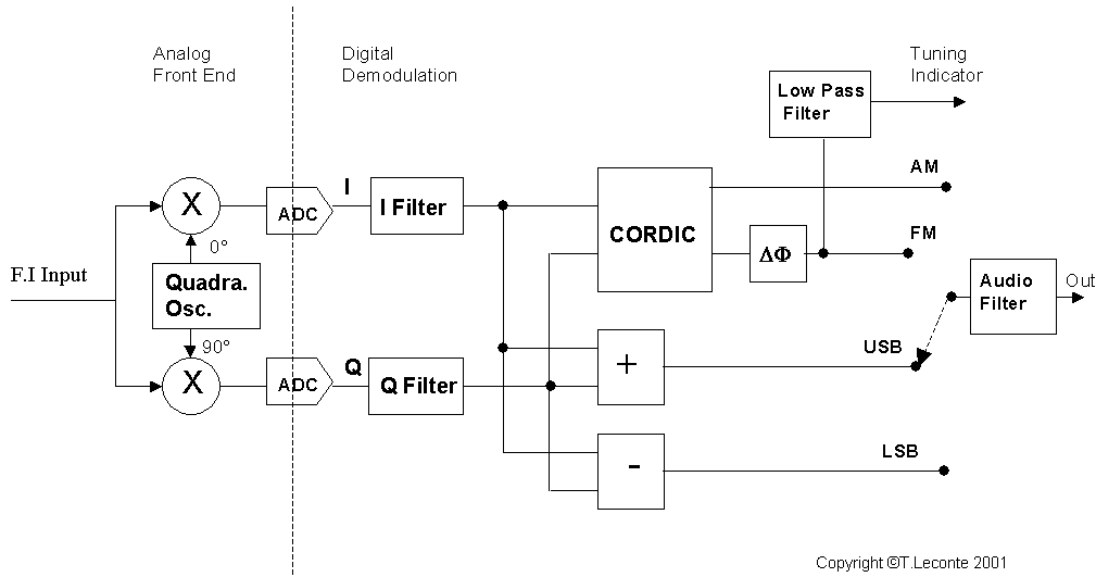
The following figure shows the signal path in this demodulator :

As the EVM56K codec is only able to sample data up to
48Khz, and because last receiver F.I are in general higher (445Khz or 10.7Mhz are usual
values), we need some analog front end to downmix the F.I.
In fact this front-end have a double task :
This is done by a pair of mixer, feed by a quadrature
oscillator at the F.I.
A quadrature oscillator have 2 outputs with a 90 degrees phase shift between the two.The
result of the mix is a complex signal in the audio range that could be sampled by EVM56K
stereo codec.
Man could implement this front end with any mixer and oscillator suitable for the given
F.I.
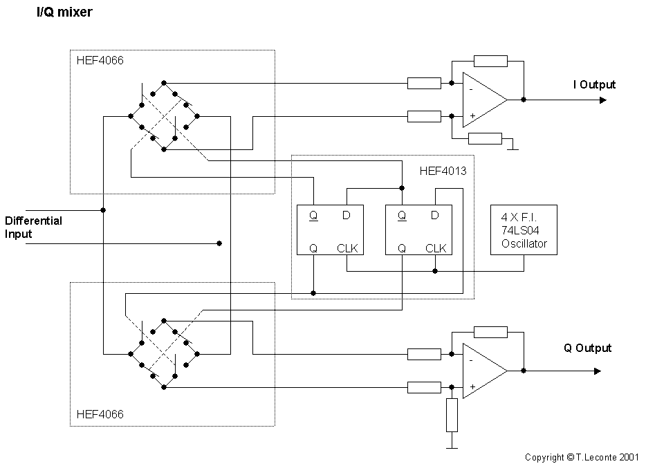
My implementation for the 455KHz F.I of my FRG-7 is highly inspired from the Philips
application note : AN1980.
It uses HEF4066 as mixer, HEF4013 and 74LS04 as quadrature oscillator and a OP249 as
Opamp:

Most of the works is done in the digital domain, by the
demod.cld program after the analog to digital conversion (ADC).
The I and Q signals, coming from the ADCs at a 9.6Khz sampling rate, are filtered by FIR
filters and send to the demodulation function.
Filters and function depend of the selected mode (AM , FM , USB or LSB).
The resulting audio signal goes to a FIR bandpass audio filter and outputted to the codec
DAC for digital to analog conversion and audio amplification.
The AM and FM demodulation is based on the CORDIC algorithm. This algo compute the phase and magnitude of a I/Q
signal.
For AM and FM the I/Q filters are just low pass filters to select only the usefull input
bandpass (2 x 6Khz).
The SSB demodulation is based on the phasing technique :
Then I and shifted Q are added or substracted together
depending of SSB mode (USB or LSB).
The great advantage of digital over analog for this technique is the ability to build a
quasi perfect digital Hilbert filter when it's very difficult in analog domain.
For a description of the background theory needed to understand how all that could work, see the very good DSP tutorial by KF6DX publied in QEX Mar/Apr 1998.
The sources are here : lcedemod01.zip
I have bought a graphical LCD display to connect it to the EVM board, in order to display the spectrum of the input signal in real-time. This will need to compute a sliding window FFT and display the result in real time.
demod.cld has already near all is needed to decode some
digital mode, in particular FSK modes like RTTY.
It could display the result on the small LCD or output the result to the EVM serial
interface for external display.
Copyrights © Thierry Leconte 2001