When someone mentions Digital Electronics, one sometimes conjures up images of complex interconnected FPGA devices or circuits where you think you might require a Phd in Sub Molecular Microscopy. This is certainly not the case and it is quite easy to get started in Digital Electronics.
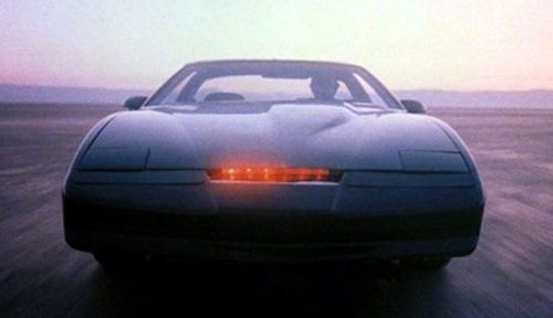
It does not have to be complex or a steep learning curve. In the 1980’s we had one particular TV series called Knight Rider, a car that was not just Bullet proof but sported “Pursuit Mode” and a rather fancy looking arrangement of LED’s tucked into the front grill. This is a simple light chaser circuit and it’s surprisingly easy to overlook this as a “Digital” circuit.
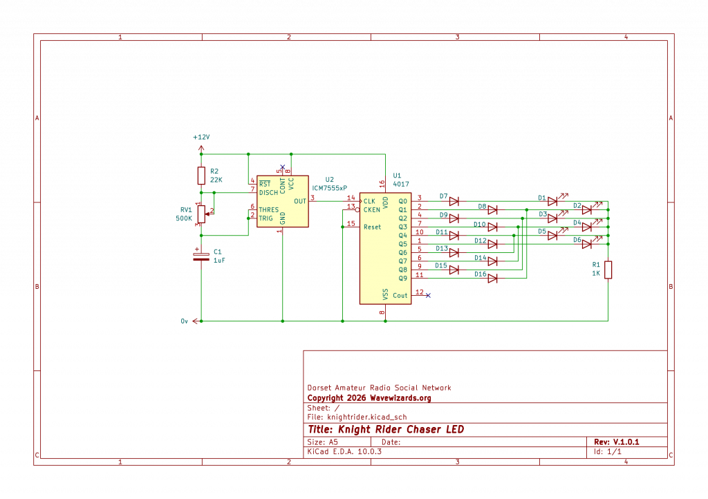
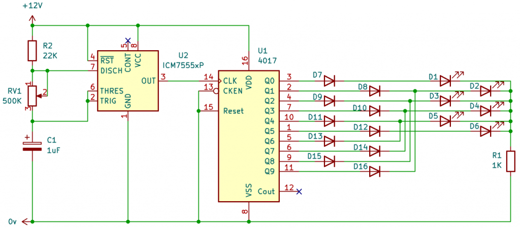
For this circuit, we are going to need a 555 Timer I.C and a CD4017 Logic chip. These are both powered by a single ended supply and a few very easy to get components.
The 555 Timer I.C. will provide a clock signal. The signal is fed into the CD4017 and each time a rising edge is detected by the 4017, the output will change. We can use this change to illuminate the connected LED’s
How does it work? The 555 Timer I.C is set as a Multi-vibrator Oscillator (Astable) This produces a clock pulse that can be set by RV1 to a speed of your liking. The clock signal is then fed into the 4017 Counter and every pulse received by the 4017 will increment the LED output accordingly. The Diodes D13, 14, 15 and 16 are used to reverse the light sweep. D1 to D6 can be any junk box LED. You can use a Triac or a Transistor to switch heavier loads or higher voltage for things like circus lights etc.
Bill of Materials
D1 – D6 = Red Led
D7 – D16 = 1N4148 Small Signal Diodes
R1 = 1K Resistor
R2 = 22K Resistor
RV1 = 500K Potentiometer
C1 = 1uF Electrolytic Capacitor
U1 = 4017 Johnson Counter (CD4017 also works)
U2 = 555 Timer I.C (Any Manufacturer will work)